
Since I never understood op-amps from reading or practicing problems I wanted to build a circuit to probe around and use different resistor values to set the amplification.
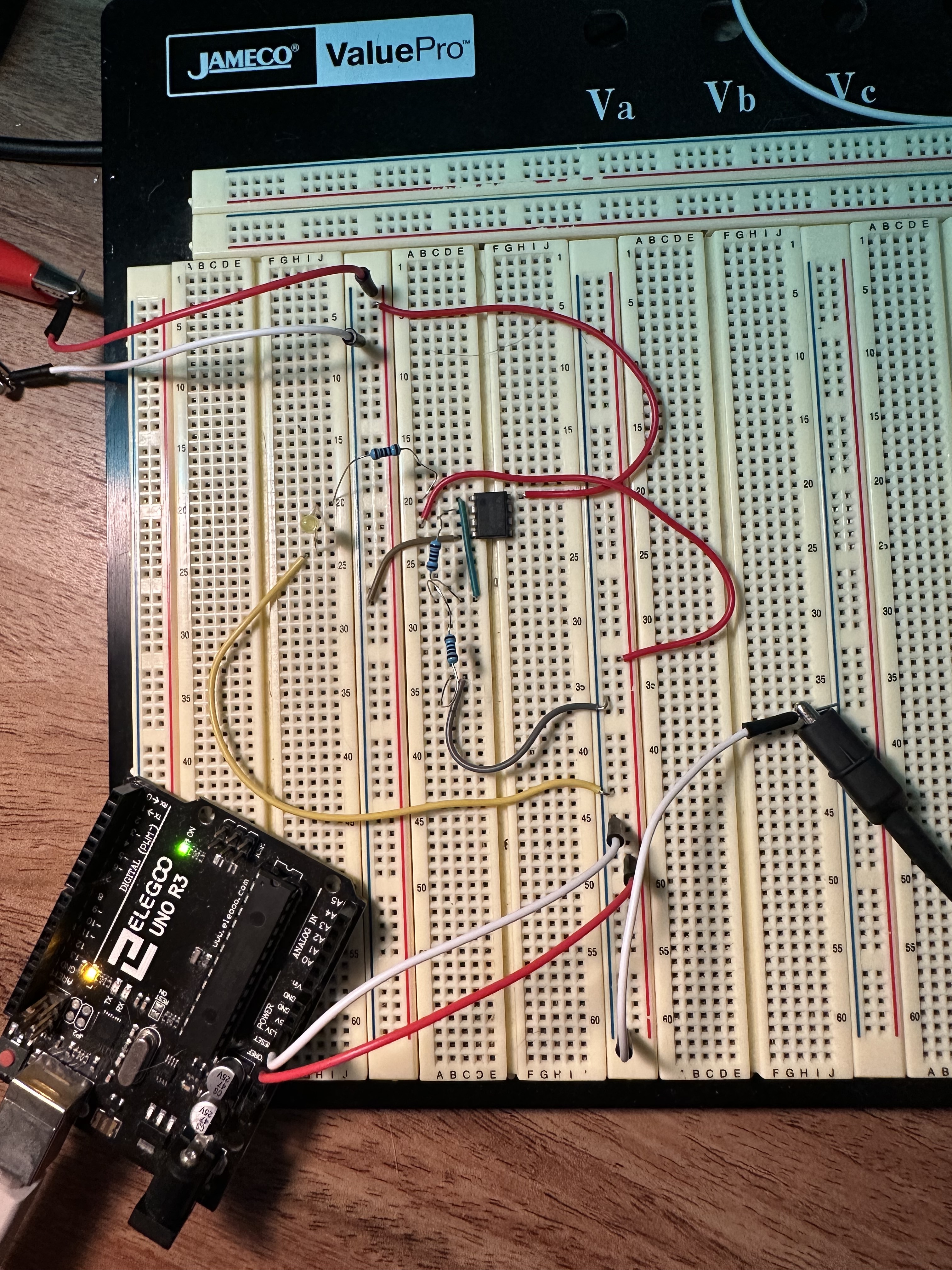
Currently I am attempting to build an LM358 Non-Inverting Op Amp. I am using my power supply for a +/- 12V rail, and my Arduino Uno for my 5V supply at the V+ input pin. I have chosen two 1k resistors to amplify the signal to 10V at the output and put and led as a indication that the circuit is working.
My questions are as follows:
- Is the ground for the voltage rail and input signal the same?
- What exactly is wrong with the circuit I built? I want the LED to only turn on when 5V is supplied at the input, right now the LED can turn on if I connect the ground to the voltage rail supply even without an input voltage.
- I’ve seen the post on Adafruit with the feedback resistors connected to the same ground as the rail supply, but the circuit diagram does not show where the input voltage ground is? Link: https://blog.adafruit.com/2012/06/13/ask-an-educator-making-a-non-inverting-op-amp-circuit-on-a-breadboard/
What worked for me, that may not do so for anyone else - is to take an existing circuit (usually a reference one provided by a manufacturer) and build that. Get that working (sometimes, it hasn’t worked- the manufacturer’s technical support department has often been very helpful, especially when their reference design has a design fault or has been misprinted - after doing that, they used to send me unmarked, pre-production chips/etc to play with and provide feedback).
Then modified that design, to test my understanding. Tried different board layouts, guard rings, etc and documented the effect. When it didn’t work as expected - took that back to their tech support to see if we could work out why.
So, for me, taking something that works and keep modifying it, just a little.