
Since I never understood op-amps from reading or practicing problems I wanted to build a circuit to probe around and use different resistor values to set the amplification.
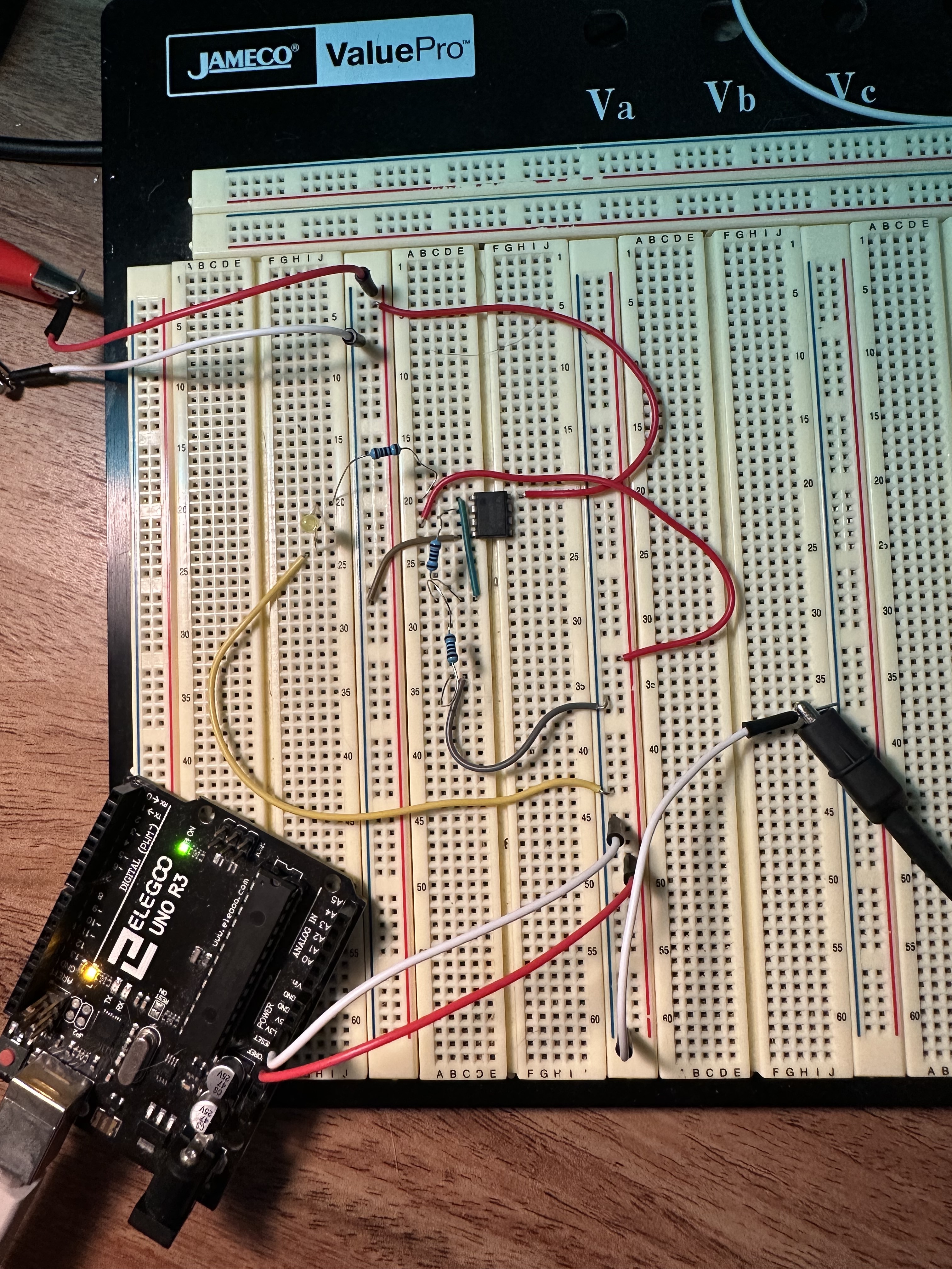
Currently I am attempting to build an LM358 Non-Inverting Op Amp. I am using my power supply for a +/- 12V rail, and my Arduino Uno for my 5V supply at the V+ input pin. I have chosen two 1k resistors to amplify the signal to 10V at the output and put and led as a indication that the circuit is working.
My questions are as follows:
- Is the ground for the voltage rail and input signal the same?
- What exactly is wrong with the circuit I built? I want the LED to only turn on when 5V is supplied at the input, right now the LED can turn on if I connect the ground to the voltage rail supply even without an input voltage.
- I’ve seen the post on Adafruit with the feedback resistors connected to the same ground as the rail supply, but the circuit diagram does not show where the input voltage ground is? Link: https://blog.adafruit.com/2012/06/13/ask-an-educator-making-a-non-inverting-op-amp-circuit-on-a-breadboard/
the first thing i’d do is connect the GND from your arduino and from your power supply. At the moment there does not seem to be a common ground or it is off picture.
The circuit works when there is a common ground (makes sense ofc but originally I thought they had to be separate), I didn’t want to put 5V and 12V on the same rail of the breadboard. Now what I find strange is that even without the 5V input voltage, I still get 10V at the output of the Op-amp which is very confusing.