
Since I never understood op-amps from reading or practicing problems I wanted to build a circuit to probe around and use different resistor values to set the amplification.
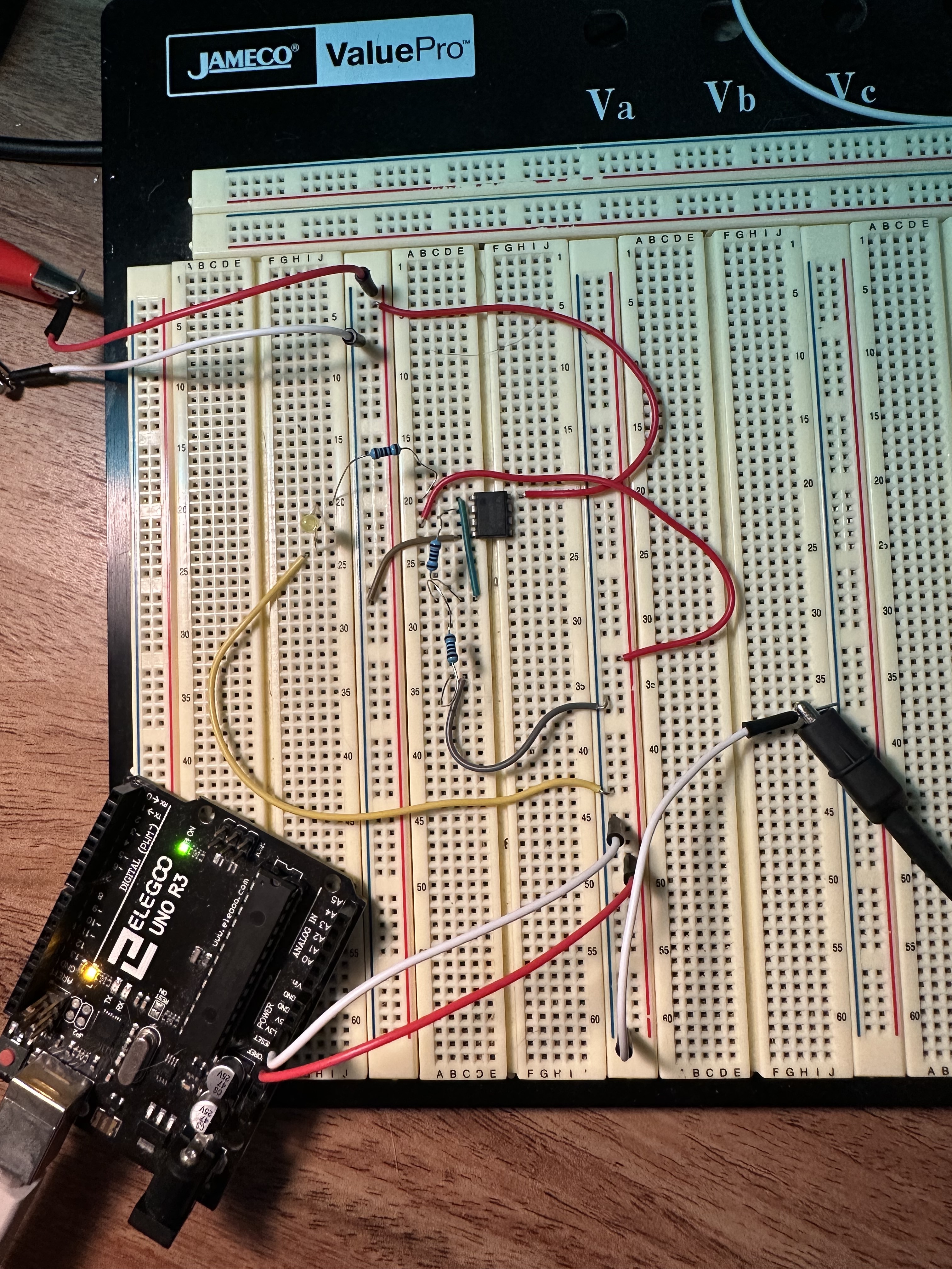
Currently I am attempting to build an LM358 Non-Inverting Op Amp. I am using my power supply for a +/- 12V rail, and my Arduino Uno for my 5V supply at the V+ input pin. I have chosen two 1k resistors to amplify the signal to 10V at the output and put and led as a indication that the circuit is working.
My questions are as follows:
- Is the ground for the voltage rail and input signal the same?
- What exactly is wrong with the circuit I built? I want the LED to only turn on when 5V is supplied at the input, right now the LED can turn on if I connect the ground to the voltage rail supply even without an input voltage.
- I’ve seen the post on Adafruit with the feedback resistors connected to the same ground as the rail supply, but the circuit diagram does not show where the input voltage ground is? Link: https://blog.adafruit.com/2012/06/13/ask-an-educator-making-a-non-inverting-op-amp-circuit-on-a-breadboard/
Yep.
Schematic of exactly what you did… not what was on paper, how it is on the breadboard.
It’s the same as the opamp’s ground.
Use a single power suppy (GND and +12V) and tie the Arduino’s GND with that GND.
Your circuit fails because the Arduino’s GND is tied to the -12V from the dual power supply, so the +5V that the Arduino outputs equal to -7V on the non-inverting input. Since this is a non-invering schematic, the opamp doesn’t invert the signal. Instead, it tries to double the -7V to get -14 on the Out, but since you’re powering the opamp with -12V, it can’t achieve a voltage that low, so it outputs the maximum it can give: -12V.
The LED turning on even when there’s no signal on the non-inverting input is probably a floating input problem. It picks up EMI so it just amplifies that. Try connecting the non-inverting input to GND, the LED should turn off… that or you burnt one of the opamps, lol, try the other one in the package.
I tied the Arduino’s GND to the power supply GND, the output is still 10V, tried different ICs as well, not really sure what the issue is at this point. Tying the non inverting input pin to ground does turn OFF the LED, but the led stays on regardless if the 5V is coming from the arduino or not, it seems that the op amp outputs 10V regardless of the non-inverting pin, however if I use different resistors to lower the gain or change the input voltage to 3.3V instead of 5V, I do get the output voltage. I just don’t understand how there can be 10V at the output with no voltage from the inverting or non-inverting pin.
Well, you should get 10V. You input 5V, the voltage gain is 2, so the output should be 10V. I don’t see a problem here, the circuit is working as expected.
But that’s the thing, it outputs 10V even when the 5V rail from Arduino is disconnected at V+ (pin 3).
Put a pot between the arduino’s +5V and the circuit, see what happens when you turn it. A 10K to 100K pot should be enough.