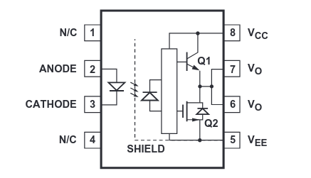
I haven’t really been able to find much on this. I recognize the totem-pole and what that’s for. Would love help understanding:
- What’s the triangle?
- What’s the rectangle immediately after?
- Why are there two outputs instead of one? A lecture I watched claimed this is common.
The triangle is an opamp. Its output (right) is the difference of inputs (left) (plus some small offset due to manufacturing tolerances) multiplied by a large number (million or more), capped to more or less the voltage of its power rails. In most uses, there is a feedback so the output influences inputs to equalize them, effectively creating an amplifier whose voltage amplification is set by rhe strength of the feedback. Without a feedback, the opamp’s output will be either GND or Vcc depending on the which input’s voltage is higher. An opamp in this configuration os known as the comparator. Basically, it flips based on whether the photodiode is generating voltage, and I think that allows for higher frequencies than a traditional phototransistor. In reality, a very large resistor (megaohms or gigaohms) is added so that the voltage on the diode actually goes below zero when no light is incoming but it was omitted from the diagram.
The rectangle looks a bit like a European-style potentiometer but it isn’t. Maybe a resistive divider?
Maybe two outputs because DIP-6 packages are uncommon and they went for the standard.
Triangle is an amplifier and rectangle is a black box (“don’t worry what’s in here, we promise it’s not gremlins”).
I suspect that the box might be a biasing array for driving the two output transistors, but then I would also expect two wires to come out of it (one for each transistor) rather than a single combined wire.
Broadcom’s datasheet for their version of the part seems to be more akin to what I’m thinking:

Could be either. You’d have to decap the chip to find out, the datasheet writers thought these details were not important.
I have no idea why two of the output pins are tied together. They’re not using many of the pins on this package so maybe they thought “why not”. I’ve also seen dual-optocouplers in this same 8 pin package where pins 6 & 7 are the outputs of the two separate couplers.
rectangle is a black box (“don’t worry what’s in here, we promise it’s not gremlins”).
It’s where they store the magic smoke.
Lol at the extra wide opamp
The triangle is an opamp, as for the other two questions… Don’t know, biasing resistor bridge? Not sure why it would have that though
It cannot be just a bridge, or else its output woukd stay constant regardless of input. There are other mandatory resistors missing in the diagram though.

