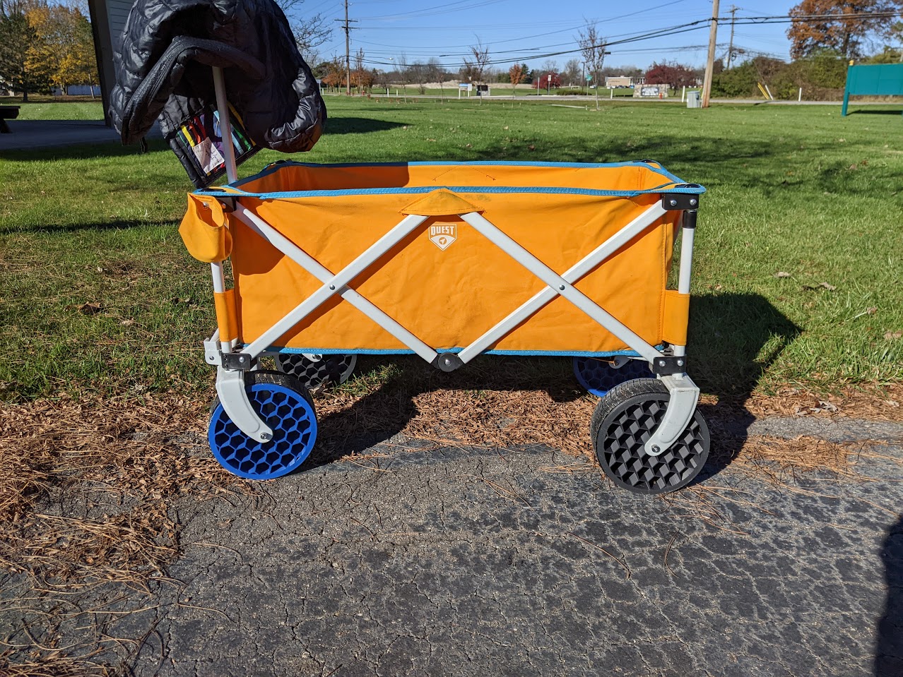
Our kids are starting to outgrow our double stroller, but will still want to ride from time to time. We’ve had this wagon for years, but it needed some upgrading. Rather than toss it and buy a new kid wagon, I decided to modify this one. Its biggest deficit was its wheels. They had metal sleeve bushings instead of real bearings and the wheels themselves were basically just an ABS doughnut with a narrow/thin rubber bands for tread. The treads had all cracked and fallen off. All this made the wagon hard to pull and loud.
I decided to make my own wheels to solve both problems. The new wheels consist of two halves and a TPU tread. The halves are keyed to mate with each other and are held together with m3 nuts/threadserts. Each half contains two skate bearings, resulting in four bearings per wheel. It’s probably overkill, but I didn’t want to leave the two halves unsupported in the center of the wheel at their interface.

Built in bridges for the somewhat weird shape to trick the slicer.

Now my 3 year old can pull me around in the wagon.
100 pounds worth of kids
That’s pretty cheap!
Hey you gotta cut corners to afford printers and filament.
I’m still confused about the bridges everyone’s talking about. Please help
This is buried lower in the thread, so here it is again: the face you see facing you in the CAD was the first layer. Note the inset faces at 1:00, 3:00, 5:00, 7:00, 9:00 and 11:00. Due to their shape and the fact that they have a hole in the middle of them, a slicer would typically just try to print from the center out in mid air.
Orienting the print the other way around wouldn’t have worked due to the way I decided the two halves to mesh - I would have been printing way more in mid air. This orientation also gives me a nice looking first layer facing out.
@[email protected] was right on the money, here are a few closer visuals. They’re only a layer thick. I’ve found that if I make them too wide the slicer will stop trying to turn them into a bridge.
CAD:

Here’s one of the earlier ones before I got the spacing down. Without it my slicer would have tried to print the circular heatsert hole in midair.

Hexagon is the bestagon!
Awesome! I wonder if something like this would be better for shock absorbing. The hexagons should work pretty well though.
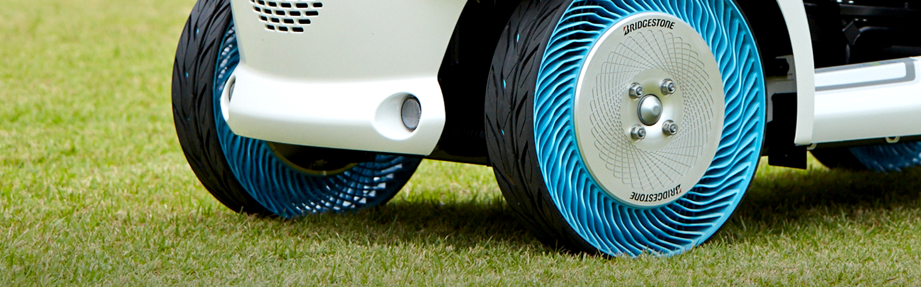
Printing your own airless tires? We’re getting close to fully downloadable car.
I saw this style wheel on a RC car recently and it got my attention. Yet another thing to go on the list…
Awesome! Which Mars rover are you gonna name the wagon after now?
We’re way more utilitarian than that given our still pretty young kids, but maybe next year. For now it will remain “the wagon”, lol. I’m really considering printing them a Hadley telescope for Christmas. They’re both aware of planets and space, and know that space proves and rovers are a thing, but it’s all a bit abstract to them right now.
I hear you-- Just saying, once you get a few kids in there, it’s going to be four wheels carrying some very sophisticated sensor and communications equipment. Sounds like a rover to me. Still early in R&D though, I get it.
Ha, totally. Give it a year or two!
I would go with something like an old Meade ETX with autostar and just print some of the eyepieces you’ll find that have lens kits you can buy. The eyepieces are nice and the prints are easy. An actual scope is a tricky project to dial in and the longer focal lengths are hard to use in practice. Something like an ETX60 is reasonably cheap and while you’ll barely see more than dot with 3-4 tiny specs of Jupiter’s moons or the haze of the Orion nebula, they are quite easy to find in practice. Doing initial alignment is also easy and forgiving. That’s just my take. I also wouldn’t mess with any of the phone camera adaptors. I ended up making my own that had 6 axis alignment, but the bubble lens and software compensation on most phones makes them mostly useless through and additional lens stack of an eyepiece.
Thanks for chiming in on the scope. Are you saying that building one from someone else’s plans might be a bit of a slog?
When they’re older, if they’re still interested in astronomy, we’ll probably do as you suggest. Honestly, it’s less about the usability scope and more about assembling one with the kid right now. I am trying to get them interested in tinkering and making things while they’re young and impressionable. We live in the middle of a large metro with tons and tons of light pollution. We’re also on the west side of the timezone, so the sun is down way past bedtime for 2/3 of the year.
Another thing on the list to print for Christmas is a pendulum clock. Our oldest likes “analog looking” watches already, although he’s too young and rambunctious to have a mechanical watch. A wall clock will do nicely though.
Optics are very precision oriented. I’ve messed with designing for optics and found it to be very challenging to make anything effective. It is not the kind of project I would build from scratch on my own without a baseline to compare the scope to. I think a Hadley is more like a second scope built for fun type of side project. I think you’d be better off with something like this: https://www.surplusshed.com/pages/item/L14481.html (no affiliation)
I mean, you can grind your own mirrors, how hard could it be? (Spoiler: very hard)
Nice work. Did you do anything with the bearings or screws?
What do you mean? The bearings are friction fit and ride pretty tightly on the 8mm bolt that runs through them. The screws that hold the two halves together screw into threadserts.
Oh I probably misunderstood you and thought you put in a bearing.
That looks amazing! Nice work. And those bridges are are such a neat trick.
Thanks! And agree, the bridges are a great trick to have in your sleeve. Someone pointed them out in the Voron STLs and I’ve been hooked ever since.
What bridges? Where? For what? I am really confused and curious!
Near the bolt holes joining the two halves, you can see thin strips going across that overhang gap. Those eliminate local sagging without needing support material. The part could have been flipped 180 instead, but then the outer edge rim would be unsupported.
@[email protected] was right on the money, here are a few closer visuals. They’re only a layer thick. I’ve found that if I make them too wide the slicer will stop trying to turn them into a bridge.
CAD:
Here’s one of the earlier ones before I got the spacing down. Without it my slicer would have tried to print the circular heatsert hole in midair.


